Turbine Block Propagation
A Solana cluster uses a multi-layer block propagation mechanism called Turbine to broadcast ledger entries to all nodes. The cluster divides itself into layers of nodes, and each node in a given layer is responsible for propagating any data it receives on to a small set of nodes in the next downstream layer. This way each node only has to communicate with a small number of nodes.
Layer Structure
The leader communicates with a special root node. The root can be thought of as
layer 0 and communicates with layer 1, which is made up of at most
DATA_PLANE_FANOUT nodes. If the number of nodes in the cluster is greater than
layer 1, then the data plane fanout mechanism adds layers below. The number of
nodes in each additional layer grows by a factor of DATA_PLANE_FANOUT.
A good way to think about this is, layer 0 starts with a single node, layer 1
starts with fanout nodes, and layer 2 will have fanout * number of nodes in
layer 1 and so on.
Layer Assignment - Weighted Selection
In order for data plane fanout to work, the entire cluster must agree on how the
cluster is divided into layers. To achieve this, all the recognized validator
nodes (the TVU peers) are shuffled with a stake weighting and stored in a
list. This list is then indexed in different ways to figure out layer boundaries
and retransmit peers - referred to as the (turbine tree). For example, the
list is shuffled and leader selects the first node to be the root node, and the
root node selects the next DATA_PLANE_FANOUT nodes to make up layer 1. The
shuffle is biased towards higher staked nodes, allowing heavier votes to come
back to the leader first. Layer 2 and lower-layer nodes use the same logic to
find their next layer peers.
To reduce the possibility of attack vectors, the list is shuffled and indexed on every shred. The turbine tree is generated from the set of validator nodes for each shred using a seed derived from the slot leader id, slot, shred index, and shred type.
Configuration Values
DATA_PLANE_FANOUT - Determines the size of layer 1. Subsequent layers grow by
a factor of DATA_PLANE_FANOUT. Layers will fill to capacity before new ones are
added, i.e if a layer isn't full, it must be the last one.
Currently, configuration is set when the cluster is launched. In the future, these parameters may be hosted on-chain, allowing modification on the fly as the cluster sizes change.
Shred Propagation Flow
During its slot, the leader node makes its initial broadcasts to a special root node (layer 0) sitting atop the turbine tree. This root node is rotated every shred based on the weighted shuffle previously mentioned. The root shares data with layer 1. Nodes in this layer then retransmit shreds to a subset of nodes in the next layer (layer 2). In general, every node in layer-1 retransmits to a unique subset of nodes in the next layer, etc, until all nodes in the cluster have received all the shreds.
To prevent redundant transmission, each node uses the deterministically
generated turbine tree, its own index in the tree, and DATA_PLANE_FANOUT to
iterate through the tree and identify downstream nodes. Each node in a layer
only has to broadcast its shreds to a maximum of DATA_PLANE_FANOUT nodes in
the next layer instead of to every TVU peer in the cluster.
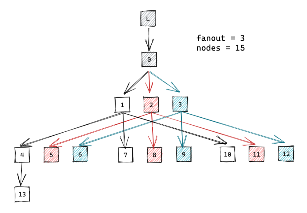
The following diagram shows how shreds propagate through a cluster with 15 nodes and a fanout of 3.
Calculating the required FEC rate
Turbine relies on retransmission of packets between validators. Due to retransmission, any network wide packet loss is compounded, and the probability of the packet failing to reach its destination increases on each hop. The FEC rate needs to take into account the network wide packet loss, and the propagation depth.
A shred group is the set of data and coding packets that can be used to reconstruct each other. Each shred group has a chance of failure, based on the likelihood of the number of packets failing that exceeds the FEC rate. If a validator fails to reconstruct the shred group, then the block cannot be reconstructed, and the validator has to rely on repair to fixup the blocks.
The probability of the shred group failing can be computed using the binomial
distribution. If the FEC rate is 16:4, then the group size is 20, and at least
4 of the shreds must fail for the group to fail. Which is equal to the sum of
the probability of 4 or more trials failing out of 20.
Probability of a block succeeding in turbine:
- Probability of packet failure:
P = 1 - (1 - network_packet_loss_rate)^2 - FEC rate:
K:M - Number of trials:
N = K + M - Shred group failure rate:
S = 1 - (SUM of i=0 -> M for binomial(prob_failure = P, trials = N, failures = i)) - Shreds per block:
G - Block success rate:
B = (1 - S) ^ (G / N) - Binomial distribution for exactly
iresults with probability of P in N trials is defined as(N choose i) * P^i * (1 - P)^(N-i)
For example:
- Network packet loss rate is 15%.
- 50k tps network generates 6400 shreds per second.
- FEC rate increases the total shreds per block by the FEC ratio.
With a FEC rate: 16:4
G = 8000P = 1 - 0.85 * 0.85 = 1 - 0.7225 = 0.2775S = 1 - (SUM of i=0 -> 4 for binomial(prob_failure = 0.2775, trials = 20, failures = i)) = 0.689414B = (1 - 0.689) ^ (8000 / 20) = 10^-203
With FEC rate of 16:16
G = 12800S = 1 - (SUM of i=0 -> 16 for binomial(prob_failure = 0.2775, trials = 32, failures = i)) = 0.002132B = (1 - 0.002132) ^ (12800 / 32) = 0.42583
With FEC rate of 32:32
G = 12800S = 1 - (SUM of i=0 -> 32 for binomial(prob_failure = 0.2775, trials = 64, failures = i)) = 0.000048B = (1 - 0.000048) ^ (12800 / 64) = 0.99045